LOGIC:
Provide definite boundaries of a state, so that a state can not be in two conditions at once.
In the logic of the rule known as follows:
– A state can not be in both right and wrong at the same time
– Each one is right / wrong.
– A condition called true when it is not wrong.
In ajabar boolean state is indicated by two constants: LOGIC “1” and “0”
Basic operations of logic and logic gates:
Definition GATE (GATE):
– The series of one or more input signals but only produce a single output signal.
– digital circuit (two-state), because the input or output signal only in the form of high voltage or low (1 or 0).
– Each output depends entirely on the signal given to the input-input.
NOT logic operations (Inverse)
Change operation logic 1 to 0 and vice versa x = x “

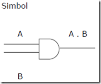
AND logic operation
– operation between the two variables (A, B)
– This operation will generate a logic 1, if the two variables are logic 1
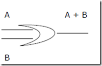
OR logic operation
– Operation between the two variables (A, B)
– This operation will generate a logic 0, if both the variable logic 0.
NOR logic operations
– This operation is an OR and NOT operations, the output is the output of the OR operation on the inverter.
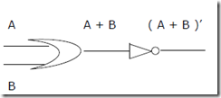
or
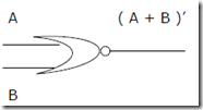
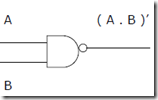
NAND logic operation
– The operation of this logic operation is a combination of AND and NOT, AND gate output is output that is in the inverter.
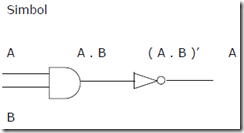
Or
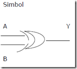
EXOR logic operation
– Will produce output “1” if the number of entries that is worth “1” odd number.
EXNOR logic operations
– This operation will produce output “1” if the number of entries that is worth “1” an even number or none at all.
