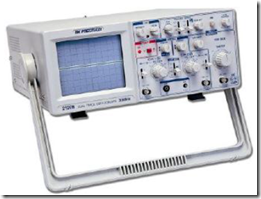
The oscilloscope is an electronic measuring instrument, used for viewing the waveform of the voltage, the prices voltage moments in the form of sinus and non-sinus. Oscilloscopes can be seen with waveform audio and video signals, waveforms Voltage Alternating Current Feedback coming from generator power plants, as well as Voltage Direct Current electricity coming from the power supply / battery. Figure 32 shows one form Oscilloscope question.

Figure 32. Oscilloscope

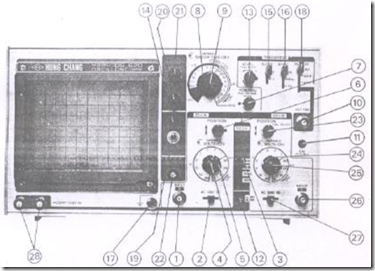
Figure 33. The front view Oscilloscope
Controls and indicators Oscilloscope
1. VERTICAL INPUT;
Serves as an input terminal for channel A / channel A.
2. AC-GND-DC.
Liaison vertical input to channel A. If the button AC-GND-DC is placed in the position of the AC, the input signal containing a DC component would be arrested / be blocked by a capacitor. If the key AC-DC-GND GND placed in a position, input terminal will open, inputs sourced from internal reinforcement in the Oscilloscope will be grounded.
If the button AC-GND-DC is placed in the position of DC, input terminal will be connected directly to the amplifier is in the Oscilloscope and the entire input signal is displayed on the monitor screen.
3. MODE
CH-A: to display waveform-channel A / channel A.
CH-B: for the waveform display channel-B / channel B.
DUAL: the measuring limit (range) between 0.5 sec / DIV – 1 msec (milli second) / DIV, both the frequency of both channels (CH-A and CH-B) will intersect at a frequency of about 200k Hz.
At the limit measure (range) between 0.5 msec / DIV – 0.2 μ sec / DIV switch reach the second measuring channel (channel / CH) are used interchangeably.
ADD: CH-A and CH-B are summed. By pressing PULL
Invert be obtained SUB MODE.
3. VOLTS / DIV variable for the channel (channel) / CH-A.
4. VOLTS / DIV Vertical attenuator (vertical attenuator) for the channel (channel) / CH-A. If the “VARIABLE” is rotated to the right (clockwise), the screen will be reflected reflected voltage per “DIV”.
Picks per “DIV” is available from 5 mV / DIV – 20V / DIV.
5. Regulatory vertical position for the channel (channel) / CH-A.
6. Regulatory horizontal position.
7. SWEEP TIME / DIV.
8. SWEEP TIME / DIV VARIABLE.
9. EXT.TRIG to trigger input signal from the outside.
10. CAL for calibrating the voltage is 0.5 V pp (peak to peak) or voltage from peak to peak.
COMP.TEST switch to change the function of Oscilloscope as the test component (component tester). To test the components, buttons SWEEP TIME / DIV in the “set” in the position of CH-B for XY mode. button AC-GND-DC to the GND position.
13. triggering LEVEL.
14. INDICATOR LIGHT.
15. SLOPE (+), (-) customizer slope polarity (waveform).
16. SYNC for mode selection switch in the position; AC, HF REJ, and TV.
17. GND terminal ground / earth / ground.
18. SOURCE election customizer signal (syncronize signal selector). If the SOURCE button at the position:
– INT: signal of channel A (CH-A) and channel B (CH-B) for the purposes of an pen-trigger / ignition mutual summed,
– CH-A: pen-trigger signal for late only from CH-A,
– CH-B: signal for pen-trigger’s only from CH-B,
– AC: AC waveform will be in accordance with the AC signal source itself,
– EXT: the incoming signal to the EXT TRIG deflected / bent adapted to the signal source.
19. POWER ON-OFF.
20. FOCUS is used to generate the optimum waveform display.
21. INTENSITY brightness control waveform display for easy viewing.
22. TRACE rotator used utuk position to see lines on the screen in order to remain in a horizontal position. A screwdriver is required to play this rotator trace.
CH-B POSITION key regulator for the use of CH-B / channel (channel) B.
23. VOLTS / DIV Vertical attenuator for CH-B.
24. VARIABLE.
25. VERTICAL INPUT Vertical input for CH-B.
26. AC-GND-DC to CH-B uses the same as the explanation contained in number 2.
Componet TEST IN terminal for the components to be tested.