Electrons to the movement requires a driving engine, which is similar to a pump, which on one side of the electrical circuit electrons “pushed into”, at the same time on the other side “pull” electrons. This machine is hereinafter referred to as generator voltage or voltage source. Thus in one clamp of the excess electron source voltage (pole), clamp the other electron deficiency (pole). So between the two clamps there is a difference in the placement of electrons. Such a situation is known as a voltage.
Electric voltage U is a difference in the placement of electrons between two points.

Figure 1.17 Source voltage
SI units are set to voltage is Volt
Symbol formula for the voltage is U
Unit symbols for the Volt is V
Division and multiplication unit:
1 MV = 1 megavolt = 1000000 V = 10 6 V
1 kV = 1 kilovolt = 1000 V = 10 3 V
1 mV = 1 millivolt = 1/1000 V = 10 -3 V
1 V = 1 microvolt = one millionth V = 10 -6 V
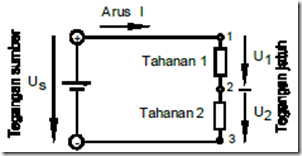
Provisions to 1V SI units are defined with the aid of electric power. In the electrical circuit to distinguish several kinds of voltage, namely the voltage source and voltage drop (see Figure 1:16).

1:18 image source voltage and voltage drop in a circuit
Voltage source (symbol Us) is the voltage generated in the voltage source.
And thus the voltage source is the cause for the occurrence of the current flow. Voltage source is distributed throughout the electrical circuit and is used in each load. As well known also as “voltage drop at the load.” From 1:18 picture, between two points anywhere on the current circuit, eg between points 1 and 2 or between points 2 and 3, the only part that is effective source voltage. Part of this voltage is called voltage drops or voltage only.
Voltage drops or general stress (symbol U) is the applied voltage at the load.
Direction voltage
Voltage always has a direction of a specific reaction, which can be illustrated by an arrow voltage. Normalization arrows voltage to the positive voltage direction indicated from the high potential (eg polar plus) to low potential (eg minus pole), in this case shows the high potential is positive and the low potential is negative.
Example :
At 1:19 the picture given an assortment of potential. How the direction of each voltage?

Pictures 1:19 arrows voltage at a given potential
To determine the current circuit is appropriate to use the normalization provision that direction. On the implementation of practice this means: Arrows voltage to the voltage source is led from pole to pole plus towards minus. Arrows voltage to the voltage fall is in line with the current direction in the technique, here the current always flows from high potential towards low potential.