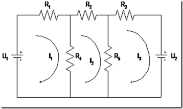
To overcome the boredom as described above, Maxwell introduced a method that calls the method of loop currents (current-loop) to solve complex problems of the electricity network. In this method Maxwell developed the rules that have been dikemukaan by Kirchoff’s Law Kirchoff in voltage and implement it through the loops are formed on the circuit concerned.
By applying the current direction, the direction of the current loop on each branch resistor can automatically follow the direction of the loop. So we no longer need to estimate specifically the current direction of each branch. Here is an example of its application.

Figure 4.6 Parallel Circuit 3 loop
From the pictures known to an electric circuit consisting of two voltage source (betere) U1 and U2 and five resistors R1, R2, R3, R4 and R5 are connected in series and parallel. To resolve this problem, Maxwell made a loop current estimates of as many as three loops with the current direction clockwise, the first loop with a current I1, the second loop to the third loop currents I2 and I3 currents.
With the loop current we will easily determine the current on each branch. For example: the current in R1 is I1, the R4 is I1 – I2, the R2 is I2, the R5 is I2 – I3 and the R3 is I3.
By applying a voltage of Kirchoff’s law to the third loop we dapatka:
Loop I
U1 – I1.R1 – (I1 – I2) .R4 = 0
I1 (R1 + R4) – I2. R4 – U1 = 0
Loop II
-I2.R2 – (I2 – I3). R5 – (I2 – I1) .R4 = 0
I1.R4 – I2. (R2 + R4 + R5) + I3.R5 = 0
Loop III
– I3.R3 – U2 – (I3 – I2) .R5 = 0
I2.R5 – I3 (R3 + R5) – U2 = 0
By finishing third loop equation that we will get all the current existing branches in the circuit.
Currency flows Jala and Matrices
N simultaneous equations on a mesh network can be written in the form of a matrix. The elements of the matrix can be used in a general form as follows:

When we apply to the application example of Maxwell loop method above, we get the following:
R11 element (row 1, column 1) is the sum of all prisoners in which the mesh current I1 through the R1 and R4. In the same way, the element R22 (row 2, column 2) and R23 (row 2, column 3) is the sum of all prisoners in I2 and I3 which flows through it.
R12 elements (lines 1, kolom2) is the sum of all prisoners in which the mesh current I1 and I2 through it. R12 is a positive sign if the two currents in the same direction through each detainee and negative when they are in the opposite direction.