Mesh current method (mesh) and the node voltage expressed by Kirchoff is the most main of direct current circuit analysis with passive element resistor (resistive circuits). However, by calculating the equivalent resistance of the branches of the series and parallel combined with the rules of the voltage divider circuit current division pad series and parallel circuits could provide another way to analyze a circuit.
But this way of course would be very boring because it usually requires additional delineation through some circuits. What else again when the circuit has many branches elements. Nevertheless, the reduction process of this series will give a clear picture of the overall function of the circuit voltage, current and power dissipated in each element of the circuit.
Examples:
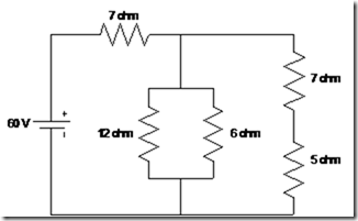
Calculate the equivalent resistance of the following resistive circuits and the total power supplied by the source of 60 V and the power absorbed by each resistor is in the network.

Figure 4.1 Circuit Combination
Completion:
Total resistance on the side ab is between detainees series 7 and 5.
Rab obtained = 12 ohm
Total resistance on the cd is a parallel between prisoners 12, 6 and 12
Obtained RCD = 12 // 6 // 12 = 3 ohms
Prisoners equivalent circuit above is the series between detainees 7 and 3.
Obtained Rek = 7 + 3 = 10 ohms.
So that the total absorbed power or the total power supplied is:
![]()