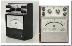
Wattmeter is an instrument for measuring the active power. Available in two forms namely analog and digital. Active power is obtained by multiplying the apparent power (S) is the multiplication of voltage (V) and current (I) and power factor (Cos α). Therefore wattmeter has two coils, namely the coil turn to detect the voltage value and the static coil to detect the current measured value. Construction Wattmeter such as are commonly referred to as a type wattmeter electrodynamic or elektrodinamometer.
The principle of the movement of the needle on the principle of rotation of the electric motor. Figure 7.3 shows a schematic diagram electrodynamic watt meter.
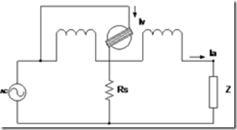
Figure 7.3 Schematic Diagram Electrodynamic Wattmeter
5:34 in the picture can be seen that the rotary spindle mounted parallel with the load so as to serve as a voltage coil and coil remain installed in series with the load so that it serves as the coil current. Scale reading calibrated in watts or kW. Electrodynamic Wattmeter This includes precision measuring instruments and can be used on a network of direct current and alternating current.
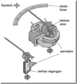
Figure 7.4 Construction electrodynamic
Electrodynamic measuring instrument has two jenisbelitan wire, the wire entanglement yangdipasang flow, and turn the coil winding wire is connected denganporos tegangansebagai and needle (Figure 5:35) .Interaksi danbelitan current magnetic field winding voltage generating pointer sudutpenyimpangan sebandingdengan load power used:
P = V · I · cos θ
The use of measuring instruments as a measure of electrical power electrodynamic atauwattmeter.Untuk purposes of measurement of electrical power wattmeter then grafting is done as follows:
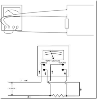
Figure 7.5 Active Power Measurement circuit with Wattmeter
Know the Power Measurement Measure Error with Wattmeter
Electrodynamic Wattmeter has a pair of coils, namely the coil current and coil voltage. How connecting the two coils will determine the value of a measuring error is obtained. For details, see the way connecting the wattmeter shown in Figure 7.7a and 7.7.b.
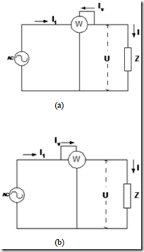
Figure 7.7 Splicing Electrodynamic Wattmeter
In Figure 7.7a, the coil current detecting load current I + Iv, and coil voltage detecting load voltage U. Consequently measured power wattmeter is coupled load power voltage coil power dissipation. Therefore, this method is suitable for the measurement of large currents.
in the figure 7.7.b, I load coil current and coil voltage detecting load voltage U + Ua. As a result, power is measured wattmeter an added load power dissipation coil current. Therefore, this method is suitable for the measurement of small currents.
