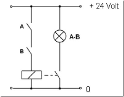
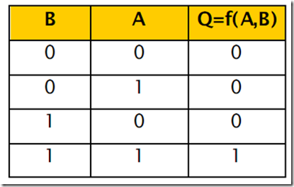
The circuit consists of two switches A and B, a relay and a lamp. The lights will only illuminate when the switch A and B are connected (on). Otherwise the lights will die if one switch or all switches disconnected (off). Can be formulated so that will only happen outputs “1” if A = “1” and B = “1”. Basic AND gate is equivalent to two open switch mounted as shown in gambar3 series. below.

2:35 The electrical circuit equivalent image AND
Electrical circuit:
Standard IEC standard symbols USA

Pictures 2:36. Symbols gate
Function equation of the AND gate
f (A, B) = AB
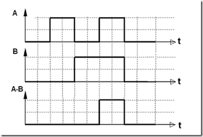
Diagram of input-output of the AND gate is seen that the output will have a logic high “1” when all inputs A and B and logic “1”

Pictures 2:37. Diagram of input-output gate
