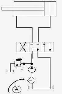
In the press line systems, filters arranged in front of the pump (arranged after the output of the pump) and before the directional control valve, the purpose of this installation is that the fluid to be entered into the hydraulic system will be entered into the hydraulic system is completely clean, these systems are usually used to protect the valve servo-valve type.
This filter must be able to withstand the maximum pressure of the system. Otherwise the filter will constrict or shrink.
Figure below shows the system circuit suction line filter system, where the filter is installed after the tank and before the pump, the fluid system will be sucked by the pump must first be through the filter, so the filter will protect the pump against fluid particles to enter. The disadvantage of this system is:
- Filters are not easily taken, because the built-in reservoir.
- There was a decrease sufficiently high pressure and cavitation arise.
- Expensive
Gear pump
Gear pumps are fixed displacement pump types. Gear pumps can be divided:
(1) gear pump with gears inside
(2) poinpa gear with external gear
Gear pump with gears inside.
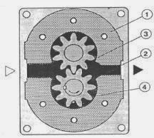
The main part is a numah (1) where there is a pair of gears that move (such that the loose in the axial and radial direction so that the unit is practically submerged oil. Part sucking (white triangles) is connected to the tank, a pressure part (black triangles) associated with hydraulic system. The gears in (2), moving in the direction of the arrow and move the gear outside (3) in the same direction. This round lead separate gears so that the cavity-free teeth into.
Gear pump with external gears
In this case the two outer gear wheels will contact each other. 2 driven gears corresponding arrows and cause the gears 3 moves opposite. Imbibing the same process occurs with this type of gear pump as described in the preceding. Fluid in space gear 4 pushed out and out of the slit on the side gears press. From the picture pieces can easily be seen gears close the gap before the passage celah- really empty. Without reducing the burden on the remaining spaces. very high pressures can occur that will cause severe vibration in the pump. To the burden placed on a deduction hole is located on the side bearing blocks. Due to high pressure, then formed then the incompressible fluid into the press room. Note that is considered important is tolerance side clearances between gears 5 and 6 bearing block.
If the tolerance is too low clearances low friction result in high leakage. If the tolerance is too high clearances result: high friction low leakage. If tolerance is designed as a gap clearances remain the leakage increases with wear. Lost volume also increased with increasing working pressure. The pump design also incorporates a balance of hydrostatic bearings. Blocks pads pushed toward the cam gear by 7 which is influenced by the system pressure. Here tolerance leeway automatically adjust to the pressure of the system. Thus produced a fairly good level of efficiency that does not depend on the speed and pressure.


