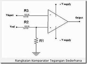
The comparator is a circuit that can compare the input voltage. The comparator usually uses Op-Amp as the primary device in the circuit. Vref is connected to + V supply, then R1 and R2 are used as voltage dividers, so the voltage value referenced to the + op-amp input is: V = [R1 / R1 + R2)]
Vsupply The op-amp will compare the voltage value of both inputs, if input (-) is greater than input (+) then the op-amp output will be equal to – Vsupply, if input voltage (-) is less than input (+ ) Then the op-amp output will be the same as + Vsupply. So in this case if the Vinput is greater than V then the output will be – Vsupply, otherwise, Vinput is greater than V then the output will be + Vsupply.
For op-amps suitable for use in op-amp circuits for comparators typically use LM339-type op-amps that are widely on the market. Comparator is an electronic circuit that will compare an input with a specific reference to produce output of two values (high and low). A comparator has two entries consisting of a reference voltage (Vreference) and an input voltage (Vinput) and an ouput voltage (Voutput).

In operation opamp will have a constant output that is worth “low” when Vin is greater than Vrefferensi and “high” when Vin is smaller than Vrefferensi or vice versa. The low and high values will be determined by the design of the comparator itself. This output state is referred to as the characteristic of the comparator output.
The work of the comparator only compares the Vin with its Vref then by adjusting the Vref, we have set the sensor sensitivity to the change of light intensity level that happened. Where the lower Vref the more sensitive the comparator to Vin voltage changes caused by changes in light intensity.