Function Generator is an electronic measuring tool generate, or generate a sine-shaped wave, triangle, ramp , rectangle, and pulse waveform. Function Generator generally generates frequency on the range of 0.5 Hz to 20 Mhz or more depends on the manufacturer’s design. The resulting frequency can be selected by rotating the frequency range button. The adjustable signal amplitude ranges from 0.1V – 20 Vp-p (peak-to-peak voltage) to no-load conditions, and 0.1V – 10Vp-p (Volt peak to peak / peak to peak voltage) with loads of 50Ω.

Figure 43. Function Generator
The main output is set by SYNC Output . The picture above shows one of the Function Generator in question.
Controls and Indicators
Function Generator comes with controls and indicators which can be used in accordance with the function of the Function Generator itself.
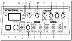
Pay attention to the control and indicator images in the Function Generator below!

Figure 44. Controls and Indicators
1. ON-OFF switch .
Press the LED indicator switch will turn on
2. FREQUENCY CONTROL
Used to set the frequency range with the multiplier of 0.04 – 4.0
3. SYNC OUTPUT
Synchronizes the TTL output surface of a rectangular signal with the frequency generated by the main output
4. SWEEP OUTPUT
Swing signals will be available regardless of switch position “SWEEP ON”
5. MAIN OUTPUT
The output signal is available normally or in swing mode depending on mode selection. Maximum output impedance 50 Ω.
6. KNOB AMPLITUDE
The aplitudo signal can be set from 0.1Vp-p to 20Vp-p under no-load conditions. If the button is pressed, the signal attenuates 10 times.
7. DC OFFSET
The button on the DC OFFSET will activate the DC voltage on the main signal. If the button is rotated clockwise will generate positive offset voltage, rotated to the opposite direction will generate negative offset voltage.
SWEEP RATE
This button is useful to set the swing speed from 5 seconds to 25 milli seconds. If this button is pressed, the operating mode of the signal swing will work.
9. SWEEP WIDHT
This button is used to set the width of the signal swing.
10. FUNCTION SELECTOR
Switch to select waveform.
11. FREQUENCY RANGE SELECTOR SWITCH
The frequency range selector switch from 10 Hz to 1MHz.
12. Hz LED
If the output frequency is in units of Hz, the green LED will light up.
13. kHz LED
If the output frequency is at kHz, the red LED lights up.
14. DIGIT DISPLAY
Digital number display to indicate the frequency generated by the patern generator , or to display the amount of input signal attached to the external input .
15. EXT COUNTER LED
If the external frequency is connected to the Patern Generator , the LED starts to count and will display a certain number.
16. COUPLING SWITCH
This switch can be placed in three positions; Internal High Frequency , External High Frequency , and External Low Frequency .
17. CMOS ADJUST KNOB
When the button is in CMOS mode, the CMOS level of the “SYNC” output will be set.
18. EXTERNAL INPUT BNC
Connector to calculate the signal from outside frequency.
19. VCF INPUT BNC
To connect AC signals or DC signals coming from outside, from 0 to 10 Volts.