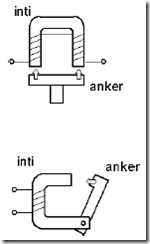
Electromagnets generate a lot of energy is used to lift the load, to move the contact on the relay and others. Moving part called the armature (Figure 1.112). This Elektronmagnet manarik haunted getting stronger, if the magnetic flux increases. This requires that the greater the flow.

1122 Sample image construction electromagnet
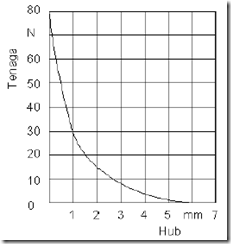
Elektromanet force the stronger the closer anchor with the core. The distance between the armature to the core is called the hub. Labor relations with the hub illustrated in Figure 1.113 below.

Image 1123. Relations with the magnetic force within the hub
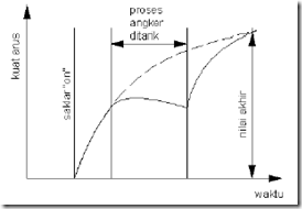
Electromagnets can be supplied with direct current or with alternating current, with little change in the core and the coil. At the time of the armature moves need attention, because at this point gap distance (distance armature to the core) is changing.

1124 Image Stream while exciting the electromagnet armature.
Magnet direct current switching process easier as shown in Figure 1124 and pull gently. At the time of switching a little warming. In the process of switching from life to death on a direct current voltage boosts will occur, which is often called the back emf. In this process often sparks leap on the switch. At the time of switching on, magnet direct current is very easy but the difficult process of releasing (pesaklaran off).
Excess direct current electromagnet will be reversed to badness alternating current electromagnet, not noisy. So widely used in hospitals, hotels and residential houses for driving eg a safety switch. To avoid bad consequences as a result of sparks and disrupt radio systems when paroses die, then dipasanglah RC circuit or voltage dependent resistors in parallel with the switch.

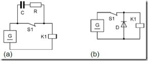
Image 1125 circuit to overcome the interference in Radio
When the switch is open (Figure 1.125a) then in a very short time current flows in the RC circuit, will thus draw current high so that the induced voltage will be obviated.
In Figure 1.125b on the condition of the switch S1 is closed (on) diode in an inverse (reverse), so that a small resistor therein. When the switch S1 is open (off), the diode will be strung forward (forward) for the induced voltage in the low back so berresistor.
Magnet alternating current using the core and the armature of the electro plate. Resistor alternating current of the coil is greater than the direct current resistor. The number of windings is also less with a wire that is greater than in direct current.
Is contrary to direct current, alternating current magnet on switching “on” will be very large while the current instantaneous voltage of the switching “on” this menekati zero. Similar installation of the RC circuit on direct current magnet, just as a function of the RC circuit to overcome when switching “on”. The amount of R and C for a working voltage of 220V ~ 50Hz is 220 for the resistor and 0,5F for capacitors.