A circuit (circuit) and Network (net work) is formed from a combination of the two terminal elements of both passive and active elements element. Active elements is a source of voltage or current source capable of delivering energy to the circuit or network. Being passive elements are resistors, inductors and capacitors are circuit elements that absorb or store energy from an energy source.
These elements can be connected in series, parallel or a combination of both.

Figure 3.1 Active Element
Figure 3.1 (a) shows the symbol of the active element, a power supply or source voltage alternating current (AC), 3.1 (b) and 3.1 (c) shows the symbol of the voltage source (DC).

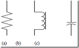
Figure 3.2 Elements of Passive (a) Resistors, (b) indusktor, (c) capacitors
Signs Agreements
When a stream enters a terminal circuit elements on the positive sign (+) to the voltage U on the element, then the absorbed power is obtained by multiplying the voltage and current or P = U x I.
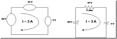
In Figure 3.3, note the voltage on the element A is Ua = 20 V, the voltage on the element B is Ub = -15 V and the voltage on the element C is Uc = 5 V. It is known much power is absorbed by elements of A are:
P = Ua x I = – (20) x (3) = – 60 watts
Negative absorption was positive emission. As a result, elements of A must be a source of tension. Power absorbed by the element B is – (-15) x (3) = 45 watts and the element C is: + (5) x (3) = 15 watts.

Figure 3.3 The agreement marks the current direction
The circuit diagram
Every circuit diagram or network can be formed or displayed in various ways. So sometimes the same circuit, but can be displayed in different forms. Therefore, in analyzing the circuit, you should first check the circuit diagram and if necessary drawn back to show more clearly how these elements relate to each other before the start solve the problem.