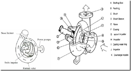
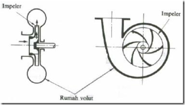
The pump consists of one or more blades are fitted with blades on the rotating shaft and covered with chasing. Fluid sucked through the suction side of the pump, due to the rotation of the blades which generate vacuum pressure. On the suction side of the fluid that has been sucked further and then thrown off the blades due to centrifugal force which is owned by the fluid.

Figure 53. Centrifugal Pumps with puff Edge
Classification of Centrifugal Pumps
a. pump Volut
The flow coming out from the blades of the pump volut accommodated in volut, which would then be channeled memalui nozzle to exit.

Figure 54. Scheme Pump Volut
b. pump difusser
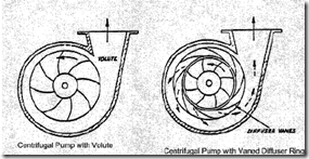
Pumps that have difusser mounted around the blade.

Figure 55. Scheme Pump difusser
Working Principle Centrifugal pump
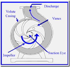
In centrifugal pumps the driving force from the outside is given to a shaft that is then used to drive a propeller or blade. The blades rotate the liquid into the pump, resulting in pressure energy and kinetic energy of the fluid increases. The liquid will be thrown out due to the centrifugal force caused by the movement of the blades. Discharge from the impeller accommodated by volut or spiral-shaped channel around the blades and supplied to the outside of the pump through the diffuser. Inside the diffuser is part of the energy velocity is converted into pressure energy.
A centrifugal pump is one of a group variable displacement pump. The nature of the variable displacement pump is the volume of water per minute is delivered is not the same as the volume of water that is sucked every minute. This was due to losses on its main components such as impellers, casing and mechanical cover. Losses that occur in the blades and casing can be caused by the design geometry and blade geometry casing.
While losses in the mechanical seals can be reduced with the user’s higher quality seal and mounting precision. Percentage losses in the impeller between 2% – 10% of the total discharge pump is delivered. Decrease in efficiency caused by inefficiency design casing reached 4.7%. The use of mechanical seals are of good quality can reduce leakage on the parts that spin, thus becoming only 10-40 cc / min.
With the reference as mentioned above, there are opportunities to improve their performance by modifying one or all of the major components of the centrifugal pump.
The design of the blades is determined by the shape of the geometry of the blades, among others, include specific speed, inner and outer diameter blades, corners inside and outside the fan (vane), width of the gap income and expenditure of the blades, the thickness of the fan and the number of fan ,
A centrifugal pump casing has two types, namely, volute (spiral) and diffuser. Casing perform functions effectively convert the centrifugal force generated by the blades into pressure. Casing designed to resemble a spiral volute type which surface area is growing towards the drain holes. Changes in the area are able to lower the speed so that the pressure to be increased.
Generally type pump single stage volute casing type. Casing type diffuser has no fan on the directional flow of water around the impeller. The water pressure always increases as it passes through the diffuser cause progressively increasing area between the fan-fan in the direction of flow.

Figure 56. The working principle of centrifugal pumps
The capacity depends on several factors such as:
- Characteristics of fluid density and viscosity, for example.
- The size of the inlet and outlet.
- The size of the blade.
- Rotation speed of the blades.
- The size and shape of the cavity between the blades
- Temperature part of suction, discharge and pressure conditions